Vlans on aironet access points configuration example
Содержание:
- Changes to this Privacy Notice
- Layer 2 Interface Modes
- VLAN Configuration Guidelines and Restrictions
- Sharing and Disclosure
- Trunk Operation
- Other Collection and Use of Information
- VLAN Default Configuration
- Allowed VLANs on a Trunk
- Chapter Information
- Collection and Use of Information
- Marketing
- Load Sharing on Trunk Ports
Changes to this Privacy Notice
We may revise this Privacy Notice through an updated posting. We will identify the effective date of the revision in the posting. Often, updates are made to provide greater clarity or to comply with changes in regulatory requirements. If the updates involve material changes to the collection, protection, use or disclosure of Personal Information, Pearson will provide notice of the change through a conspicuous notice on this site or other appropriate way. Continued use of the site after the effective date of a posted revision evidences acceptance. Please contact us if you have questions or concerns about the Privacy Notice or any objection to any revisions.
Last Update: November 17, 2020
Layer 2 Interface Modes
|
Mode |
Function |
|---|---|
|
Puts the interface (access port) into permanent nontrunking mode and negotiates to convert the link into a nontrunk link. The interface becomes a nontrunk interface regardless of whether or not the neighboring interface is a trunk interface. |
|
|
switchport mode dynamic auto |
Makes the interface able to convert the link to a trunk link. The interface |
|
switchport mode dynamic desirable |
Makes the interface actively attempt to convert the link to a trunk link. |
|
Puts the interface into permanent trunking mode and negotiates to convert the neighboring link into a trunk link. The interface becomes a trunk interface even if the neighboring interface is not a trunk interface. |
|
|
switchport nonegotiate |
Prevents the interface from generating DTP frames. You can use this command |
|
switchport mode dot1q-tunnel |
Configures the interface as a tunnel (nontrunking) port to be connected in an asymmetric link with an IEEE 802.1Q trunk port. The IEEE 802.1Q tunneling is used to maintain customer VLAN integrity across a service provider network. |
Related Concepts
VLAN Configuration Guidelines and Restrictions
When creating and modifying VLANs in your network, follow these guidelines and restrictions:
•Supervisor engine redundancy does not support nondefault VLAN data file names or locations. Do not enter the vtp file file_name command on a switch that has a redundant supervisor engine.
•Before installing a redundant supervisor engine, enter the no vtp file command to return to the default configuration.
•RPR+ redundancy (see ) does not support a configuration entered in VLAN database mode. Use global configuration mode with RPR+ redundancy.
•You can configure extended-range VLANs only in global configuration mode. You cannot configure extended-range VLANs in VLAN database mode. See the .
•Before you can create a VLAN, the switch must be in VTP server mode or VTP transparent mode. For information on configuring VTP, see
•The VLAN configuration is stored in the vlan.dat file, which is stored in nonvolatile memory. You can cause inconsistency in the VLAN database if you manually delete the vlan.dat file. If you want to modify the VLAN configuration or VTP, use the commands described in this guide and in the Cisco IOS Software Releases 12.2SX Command References publication.
•To do a complete backup of your configuration, include the vlan.dat file in the backup.
•The Cisco IOS end command is not supported in VLAN database mode.
•You cannot enter Ctrl-Z to exit VLAN database mode.
•Cisco IOS Software Release 12.2SX does not support Token Ring or FDDI media. The switch does not forward FDDI, FDDI-Net, TrCRF, or TrBRF traffic, but it can propagate the VLAN configuration through VTP.
•In VTP server mode, you can configure FDDI and Token Ring VLANs from the switch.
•You must configure a TrBRF before you configure the TrCRF (the parent TrBRF VLAN you specify must exist).
•In a Token Ring environment, the logical interfaces (the connection between the TrBRF and the TrCRF) of the TrBRF are placed in a blocked state if either of these conditions exists:
–The TrBRF is running the IBM STP, and the TrCRF is in SRT mode.
–The TrBRF is running the IEEE STP, and the TrCRF is in SRB mode.
Sharing and Disclosure
Pearson may disclose personal information, as follows:
- As required by law.
- With the consent of the individual (or their parent, if the individual is a minor)
- In response to a subpoena, court order or legal process, to the extent permitted or required by law
- To protect the security and safety of individuals, data, assets and systems, consistent with applicable law
- In connection the sale, joint venture or other transfer of some or all of its company or assets, subject to the provisions of this Privacy Notice
- To investigate or address actual or suspected fraud or other illegal activities
- To exercise its legal rights, including enforcement of the Terms of Use for this site or another contract
- To affiliated Pearson companies and other companies and organizations who perform work for Pearson and are obligated to protect the privacy of personal information consistent with this Privacy Notice
- To a school, organization, company or government agency, where Pearson collects or processes the personal information in a school setting or on behalf of such organization, company or government agency.
Trunk Operation
Well we need to trunk those switches together. We’ll change our encapsulation really. We’ll change the language that we speak across that link just a little bit and we’ll further identify the VLAN for the frames that traverse that link. That’s a trunk, okay? Now if you’re struggling with this, I want you to think about the challenge — a link, by default, is an access link and it lacks this trunking mechanism. And therefore, one link can only carry one VLAN’s worth of traffic, because we can’t discretely identify which VLAN a frame would be part of. So think about the fact that multiple switches will generally be part of the broadcast domain that the VLAN lives in and we’re going to have potentially hundreds of VLANs in one given space. Certainly, it’s quite common to see 15 to 50 VLANs in a common space to the access layer. So now we have a really big challenge. We might have a gigabit link or a 10 Gb link between our switches, and carrying one VLAN isn’t sufficient, is it? So we choose to make that a trunk link and voilà, our connectivity problem is solved. We still might have a bottleneck, but the VLANs can then flow. So this is a big deal, isn’t it? And we have to think to ourselves, okay, switch-to-switch connections should probably be trunk links, right? Also, switch to multilayer switch or switch to router, because those devices would have to terminate and route for the different VLANs. So all things being equal, when I look at a topology, I think all the links that are going down to PCs, those are going to be access ports, they’re not going to be trunks. And then, the links between my switches, those I’m going to make trunks.
This trunk link has to keep track of which VLAN that traffic belongs to, so it’s going to be tagging. But is every single VLAN tagged when we send traffic over that trunk?
There is an exception to every rule, right? At least, that’s very true here. The trunking protocol that we use in modern day Cisco is 802.1Q. You might see Inter-Switch Link, or ISL, nothing wrong with that, but we’re talking about 802.1Q – the standardized trunking technology. The Institute of Electrical and Electronics Engineers, or IEEE, who designed it, baked in the untagged VLAN called the native VLAN, a default to VLAN 1 and it can be changed. If you change it, make sure you change it on both sides of the trunk link and it, in fact, is a security challenge, so we choose to change it often to 99 or 999. So one of the 4,094 VLANs that could flow, one of them is untagged. That’s the native VLAN, defaults to 1.
Other Collection and Use of Information
Application and System Logs
Pearson automatically collects log data to help ensure the delivery, availability and security of this site. Log data may include technical information about how a user or visitor connected to this site, such as browser type, type of computer/device, operating system, internet service provider and IP address. We use this information for support purposes and to monitor the health of the site, identify problems, improve service, detect unauthorized access and fraudulent activity, prevent and respond to security incidents and appropriately scale computing resources.
Web Analytics
Pearson may use third party web trend analytical services, including Google Analytics, to collect visitor information, such as IP addresses, browser types, referring pages, pages visited and time spent on a particular site. While these analytical services collect and report information on an anonymous basis, they may use cookies to gather web trend information. The information gathered may enable Pearson (but not the third party web trend services) to link information with application and system log data. Pearson uses this information for system administration and to identify problems, improve service, detect unauthorized access and fraudulent activity, prevent and respond to security incidents, appropriately scale computing resources and otherwise support and deliver this site and its services.
Cookies and Related Technologies
This site uses cookies and similar technologies to personalize content, measure traffic patterns, control security, track use and access of information on this site, and provide interest-based messages and advertising. Users can manage and block the use of cookies through their browser. Disabling or blocking certain cookies may limit the functionality of this site.
VLAN Default Configuration
Tables through show the default configurations for the different VLAN media types.
Table 17-2 Ethernet VLAN Defaults and Ranges
Parameter
Default
Range
VLAN ID
1
1-4094
VLAN name
«default» for VLAN 1″VLANvlan_ID» for other Ethernet VLANs
—
802.10 SAID
10vlan_ID
100001-104094
MTU size
1500
1500-18190
Translational bridge 1
0-1005
Translational bridge 2
0-1005
VLAN state
active
active, suspend
Pruning eligibility
VLANs 2-1001 are pruning eligible; VLANs 1006-4094 are not pruning eligible.
—
Table 17-3 FDDI VLAN Defaults and Ranges
Parameter
Default
Range
VLAN ID
1002
1-1005
VLAN name
«fddi-default»
—
802.10 SAID
101002
1-4294967294
MTU size
1500
1500-18190
Ring number
1-4095
Parent VLAN
0-1005
Translational bridge 1
0-1005
Translational bridge 2
0-1005
VLAN state
active
active, suspend
Table 17-4 Token Ring (TrCRF) VLAN Defaults and Ranges
Parameter
Default
Range
VLAN ID
1003
1-1005
VLAN name
«token-ring-default»
—
802.10 SAID
101003
1-4294967294
Ring Number
1-4095
MTU size
VTPv1 default 1500VTPv2 default 4472
1500-18190
Translational bridge 1
0-1005
Translational bridge 2
0-1005
VLAN state
active
active, suspend
srb
srb, srt
ARE max hops
7
0-13
STE max hops
7
0-13
Backup CRF
disabled
disable; enable
Table 17-5 FDDI-Net VLAN Defaults and Ranges
Parameter
Default
Range
VLAN ID
1004
1-1005
VLAN name
«fddinet-default»
—
802.10 SAID
101004
1-4294967294
MTU size
1500
1500-18190
Bridge number
1
0-15
STP type
ieee
auto, ibm, ieee
VLAN state
active
active, suspend
Table 17-6 Token Ring (TrBRF) VLAN Defaults and Ranges
Parameter
Default
Range
VLAN ID
1005
1-1005
VLAN name
«trnet-default»
—
802.10 SAID
101005
1-4294967294
MTU size
VTPv1 1500; VTPv2 4472
1500-18190
Bridge number
1
0-15
STP type
ibm
auto, ibm, ieee
VLAN state
active
active, suspend
Allowed VLANs on a Trunk
By default, a trunk port sends traffic to and receives traffic from all VLANs. All VLAN
IDs, 1 to 4094, are allowed on each trunk. However, you can remove VLANs from the
allowed list, preventing traffic from those VLANs from passing over the trunk.
To reduce the risk of spanning-tree loops or storms, you can disable VLAN 1 on any individual VLAN trunk port by removing VLAN 1 from the allowed list. When you remove VLAN 1 from a trunk port, the interface continues to send and receive management traffic, for example, Cisco Discovery Protocol (CDP), Port Aggregation Protocol (PAgP), Link Aggregation Control Protocol (LACP), DTP, and VTP in VLAN 1.
If a trunk port with VLAN 1 disabled is converted to a nontrunk port, it is added to the
access VLAN. If the access VLAN is set to 1, the port will be added to VLAN 1,
regardless of the switchport trunk allowed setting. The same
is true for any VLAN that has been disabled on the port.
A trunk port can become a member of a VLAN if the VLAN is enabled, if VTP knows of the VLAN, and if the VLAN is in the allowed list for the port. When VTP detects a newly enabled VLAN and the VLAN is in the allowed list for a trunk port, the trunk port automatically becomes a member of the enabled VLAN. When VTP detects a new VLAN and the VLAN is not in the allowed list for a trunk port, the trunk port does not become a member of the new VLAN.
Chapter Information
Contents
- «Do I Know This Already?» Quiz
- VLAN Routing with Router 802.1Q Trunks
- VLAN Routing with Layer 3 Switch SVIs
- VLAN Routing with Layer 3 Switch Routed Ports
- Chapter Review
- Review All the Key Topics
- Key Terms You Should Know
- Command References
Chapter Description
In this sample chapter from CCNA 200-301 Official Cert Guide, Volume 1, Wendell Odom discusses the configuration and verification steps related to three methods of routing between VLANs with three major sections: VLAN Routing with Router 802.1Q Trunks, VLAN Routing with Layer 3 Switch SVIs, and VLAN Routing with Layer 3 Switch Routed Ports.
Collection and Use of Information
To conduct business and deliver products and services, Pearson collects and uses personal information in several ways in connection with this site, including:
Surveys
Pearson may offer opportunities to provide feedback or participate in surveys, including surveys evaluating Pearson products, services or sites. Participation is voluntary. Pearson collects information requested in the survey questions and uses the information to evaluate, support, maintain and improve products, services or sites; develop new products and services; conduct educational research; and for other purposes specified in the survey.
Contests and Drawings
Occasionally, we may sponsor a contest or drawing. Participation is optional. Pearson collects name, contact information and other information specified on the entry form for the contest or drawing to conduct the contest or drawing. Pearson may collect additional personal information from the winners of a contest or drawing in order to award the prize and for tax reporting purposes, as required by law.
Marketing
Pearson may send or direct marketing communications to users, provided that
- Pearson will not use personal information collected or processed as a K-12 school service provider for the purpose of directed or targeted advertising.
- Such marketing is consistent with applicable law and Pearson’s legal obligations.
- Pearson will not knowingly direct or send marketing communications to an individual who has expressed a preference not to receive marketing.
- Where required by applicable law, express or implied consent to marketing exists and has not been withdrawn.
Pearson may provide personal information to a third party service provider on a restricted basis to provide marketing solely on behalf of Pearson or an affiliate or customer for whom Pearson is a service provider. Marketing preferences may be changed at any time.
Load Sharing on Trunk Ports
Load sharing divides the bandwidth supplied by parallel trunks connecting switches. To avoid loops, STP normally blocks all but one parallel link between switches. Using load sharing, you divide the traffic between the links according to which VLAN the traffic belongs.
You configure load sharing on trunk ports by using STP port priorities or STP path costs. For load sharing using STP port priorities, both load-sharing links must be connected to the same switch. For load sharing using STP path costs, each load-sharing link can be connected to the same switch or to two different switches.
Network Load Sharing Using STP Priorities
When two ports on the same switch form a loop, the switch uses the STP port priority to decide which port is enabled and which port is in a blocking state. You can set the priorities on a parallel trunk port so that the port carries all the traffic for a given VLAN. The trunk port with the higher priority (lower values) for a VLAN is forwarding traffic for that VLAN. The trunk port with the lower priority (higher values) for the same VLAN remains in a blocking state for that VLAN. One trunk port sends or receives all traffic for the VLAN.
Figure 2. Load Sharing by Using STP Port Priorities.
This figure shows two trunks connecting supported switches.
-
VLANs 8 through 10 are assigned a port priority of 16 on Trunk 1.
-
VLANs 3 through 6 retain the default port priority of 128 on Trunk 1.
-
VLANs 3 through 6 are assigned a port priority of 16 on Trunk 2.
-
VLANs 8 through 10 retain the default port priority of 128 on Trunk 2.
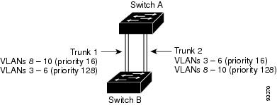
Trunk 1 carries traffic for VLANs 8 through 10, and Trunk 2 carries traffic for VLANs 3 through 6. If the active trunk fails, the trunk with the lower priority takes over and carries the traffic for all of the VLANs. No duplication of traffic occurs over any trunk port.
Related Tasks