Cisco nexus 5000 series nx-os software configuration guide
Содержание:
- Configuration – Switchport Mode Trunk
- Cisco Switch Port Commands
- Trunk Operation
- Allowed VLANs on a Trunk
- Дополнительные сведения
- Creating and Managing Cisco VLANS
- Creating Cisco Trunks
- Allen White
- Load Sharing on Trunk Ports
- Layer 2 Interface Modes
- Difference between Switchport Mode – Access and Trunk
- Предварительные условия
- Different Types of Switchport – Access & Trunk
- Configuration – Switchport Mode Access
Configuration – Switchport Mode Trunk
In this session, we will configure the switchport as a trunk. As we previously discussed, a trunk port is used to carry multiple VLAN traffic.
Below is the trunk port configuration for Cisco IOS Switches:
GNS3Network_SW2# configure terminal
Enter configuration commands, one per line. End with CNTL/Z.
GNS3Network_SW2(config)# interface FastEthernet 0/1
GNS3Network_SW2(config-if)#switchport mode trunk
GNS3Network_SW2(config-if)#end
GNS3Network_SW2#
By default, the trunk will be the member of all VLANs configured on the switch. So, it will carry out the traffic of each VLAN configured on the switch. You can restrict the switch to send the traffic of a particular VLAN using the below command:
GNS3Network_SW2# configure terminal
Enter configuration commands, one per line. End with CNTL/Z.
GNS3Network_SW2(config)# interface FastEthernet 0/1
GNS3Network_SW2(config-if)# switchport mode trunk
GNS3Network_SW2(config-if)# switchport trunk allowed vlan 10-11
GNS3Network_SW2(config-if)#end
GNS3Network_SW2#
Cisco Switch Port Commands
To manage your Cisco switch you need to understand how you access ports and how you can enable and disable them. Most switches have Fast Ethernet and Gigabit capability, newer switches have the capability of fiber and faster. Bare in mind when trying to access a port you need to take into account the type of port you are trying to access. To start accessing ports we need to start by being in enable mode. From your switch enter the following.
enable
We then need to enter the configure terminal command.
conf t
Your switch will look something like this, we now have access to the commands required to manage Cisco ports.
To access ports we use the Interface command, we then add on the port type which in the case is either Fast Ethernet or Gigabit. Here we will be accessing port 10. To access port 10 if it is Fast Ethernet we issue the command below.
interface fastEthernet 0/10
You will now be in the interface context as seen here.
If port 10 was gigabit we would of issued this command.
interface gigabitEthernet 0/10
Now that we are in the port we would like to configure we can issue the following commands.
To shut down the port issue the below command.
sh
To enable the port again issue the command below.
no sh
We can also enable or disable a range of ports with the following command, here we select port 2-5 then shut them down.
interface range fastEthernet 0/2 -5
To go back to the previous context we issue the exit command. Now that you can access your ports and enable and disable as required we are now ready to create and manage Cisco VLANS.
Trunk Operation
Well we need to trunk those switches together. We’ll change our encapsulation really. We’ll change the language that we speak across that link just a little bit and we’ll further identify the VLAN for the frames that traverse that link. That’s a trunk, okay? Now if you’re struggling with this, I want you to think about the challenge — a link, by default, is an access link and it lacks this trunking mechanism. And therefore, one link can only carry one VLAN’s worth of traffic, because we can’t discretely identify which VLAN a frame would be part of. So think about the fact that multiple switches will generally be part of the broadcast domain that the VLAN lives in and we’re going to have potentially hundreds of VLANs in one given space. Certainly, it’s quite common to see 15 to 50 VLANs in a common space to the access layer. So now we have a really big challenge. We might have a gigabit link or a 10 Gb link between our switches, and carrying one VLAN isn’t sufficient, is it? So we choose to make that a trunk link and voilà, our connectivity problem is solved. We still might have a bottleneck, but the VLANs can then flow. So this is a big deal, isn’t it? And we have to think to ourselves, okay, switch-to-switch connections should probably be trunk links, right? Also, switch to multilayer switch or switch to router, because those devices would have to terminate and route for the different VLANs. So all things being equal, when I look at a topology, I think all the links that are going down to PCs, those are going to be access ports, they’re not going to be trunks. And then, the links between my switches, those I’m going to make trunks.
This trunk link has to keep track of which VLAN that traffic belongs to, so it’s going to be tagging. But is every single VLAN tagged when we send traffic over that trunk?
There is an exception to every rule, right? At least, that’s very true here. The trunking protocol that we use in modern day Cisco is 802.1Q. You might see Inter-Switch Link, or ISL, nothing wrong with that, but we’re talking about 802.1Q – the standardized trunking technology. The Institute of Electrical and Electronics Engineers, or IEEE, who designed it, baked in the untagged VLAN called the native VLAN, a default to VLAN 1 and it can be changed. If you change it, make sure you change it on both sides of the trunk link and it, in fact, is a security challenge, so we choose to change it often to 99 or 999. So one of the 4,094 VLANs that could flow, one of them is untagged. That’s the native VLAN, defaults to 1.
Allowed VLANs on a Trunk
By default, a trunk port sends traffic to and receives traffic from all VLANs. All VLAN
IDs, 1 to 4094, are allowed on each trunk. However, you can remove VLANs from the
allowed list, preventing traffic from those VLANs from passing over the trunk.
To reduce the risk of spanning-tree loops or storms, you can disable VLAN 1 on any individual VLAN trunk port by removing VLAN 1 from the allowed list. When you remove VLAN 1 from a trunk port, the interface continues to send and receive management traffic, for example, Cisco Discovery Protocol (CDP), Port Aggregation Protocol (PAgP), Link Aggregation Control Protocol (LACP), DTP, and VTP in VLAN 1.
If a trunk port with VLAN 1 disabled is converted to a nontrunk port, it is added to the
access VLAN. If the access VLAN is set to 1, the port will be added to VLAN 1,
regardless of the switchport trunk allowed setting. The same
is true for any VLAN that has been disabled on the port.
A trunk port can become a member of a VLAN if the VLAN is enabled, if VTP knows of the VLAN, and if the VLAN is in the allowed list for the port. When VTP detects a newly enabled VLAN and the VLAN is in the allowed list for a trunk port, the trunk port automatically becomes a member of the enabled VLAN. When VTP detects a new VLAN and the VLAN is not in the allowed list for a trunk port, the trunk port does not become a member of the new VLAN.
Дополнительные сведения
- Настройка магистралей VLAN на портах Fast Ethernet Gigabit Ethernet – коммутатор Catalyst 5000
- Настройка портов LAN для коммутирования уровня 2 – коммутатор Catalyst 6500 с программным обеспечением Cisco IOS
- Настройка VTP в коммутаторах Catalyst
- Использование режима PortFast и других команд для устранения задержек соединения во время запуска рабочей станции
- Коммутаторы серии Catalyst 3560: руководство по настройке
- Коммутаторы серии Catalyst 4500: руководство по настройке
- Коммутаторы серии Catalyst 6500: руководство по настройке
- Страницы поддержки продуктов для LAN
- Страница поддержки коммутационных решений для LAN
- Cisco Systems – техническая поддержка и документация
Creating and Managing Cisco VLANS
Creating VLANS on is very simple, as long as you are in configure terminal you issue the commands as seen below, here we create VLAN 10,20 and 30.
vlan 10,20,30
If we want to assign IP addresses to our VLANS we first need to be in the actual VLAN context, here we configure VLAN 10`s ip address.First we enter vlan 10
int vlan 10
Then we allocate it the address 192.168.10.1 specifying the correct subnet. This is called Cisco VLAN Routing.
IP Address 192.168.10.1 255.255.255.0
To remove the vlan we would use the no command, for example
no vlan 10
To enable routing between our VLANs we would need to enable IP routing.
ip routing
You can now create VLANs and allocate ip address to VLANs for whatever VLANs you create, IP routing is enabled so traffic will flow. We can now create trunk ports to allow VLAN traffic to flow through our ports
Creating Cisco Trunks
In this section we select ports, then we select what VLAN traffic is allowed across these trunks. First we select our ports, we can either select a range or individual ports. To select non concurrent ports use comma “,” between ports as opposed to a hyphen as I use here. Here we select port 10-15 and allow VLAN 10 and 20 to flow, we then allow port 16-20 for VLAN. We set the encapsulation as DOT1q.
int range fastEthernet  0/10 - 15
switchport encapsulation dot1q
switchport mode trunk
switchport trunk  allowed  vlan 10,20
If we wanted to remove vlans from cisco trunks then we issue the following command, here we remove VLANs 20 and 30 from ports 10 to 15.
int range fastEthernet  0/10 - 15
no switchport trunk  allowed  vlan 10,20
For more indepth Cisco Vlan information check out http://www.cisco.com/en/US/docs/switches/lan/catalyst2950/software/release/12.1_9_ea1/configuration/guide/swvlan.html
Tags: Cisco, ports, trunks, vlan
Allen White
Allen is an IT Consultant and holds the following accreditations. MCSA, MCSE, MCTS, MCITP, CCA, CCSP, VCP 4,5, 6 and HP ASE, AIS — Network Infrastructure.
Load Sharing on Trunk Ports
Load sharing divides the bandwidth supplied by parallel trunks connecting switches. To avoid loops, STP normally blocks all but one parallel link between switches. Using load sharing, you divide the traffic between the links according to which VLAN the traffic belongs.
You configure load sharing on trunk ports by using STP port priorities or STP path costs. For load sharing using STP port priorities, both load-sharing links must be connected to the same switch. For load sharing using STP path costs, each load-sharing link can be connected to the same switch or to two different switches.
Network Load Sharing Using STP Priorities
When two ports on the same switch form a loop, the switch uses the STP port priority to decide which port is enabled and which port is in a blocking state. You can set the priorities on a parallel trunk port so that the port carries all the traffic for a given VLAN. The trunk port with the higher priority (lower values) for a VLAN is forwarding traffic for that VLAN. The trunk port with the lower priority (higher values) for the same VLAN remains in a blocking state for that VLAN. One trunk port sends or receives all traffic for the VLAN.
Figure 2. Load Sharing by Using STP Port Priorities.
This figure shows two trunks connecting supported switches.
-
VLANs 8 through 10 are assigned a port priority of 16 on Trunk 1.
-
VLANs 3 through 6 retain the default port priority of 128 on Trunk 1.
-
VLANs 3 through 6 are assigned a port priority of 16 on Trunk 2.
-
VLANs 8 through 10 retain the default port priority of 128 on Trunk 2.
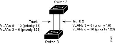
Trunk 1 carries traffic for VLANs 8 through 10, and Trunk 2 carries traffic for VLANs 3 through 6. If the active trunk fails, the trunk with the lower priority takes over and carries the traffic for all of the VLANs. No duplication of traffic occurs over any trunk port.
Related Tasks
Layer 2 Interface Modes
|
Mode |
Function |
|---|---|
|
switchport mode access |
Puts the interface (access port) into permanent nontrunking mode and negotiates to convert the link into a nontrunk link. The interface becomes a nontrunk interface regardless of whether or not the neighboring interface is a trunk interface. |
|
switchport mode dynamic auto |
Makes the interface able to convert the link to a trunk link. The interface |
|
switchport mode dynamic desirable |
Makes the interface actively attempt to convert the link to a trunk link. |
|
switchport mode trunk |
Puts the interface into permanent trunking mode and negotiates to convert the neighboring link into a trunk link. The interface becomes a trunk interface even if the neighboring interface is not a trunk interface. |
|
switchport nonegotiate |
Prevents the interface from generating DTP frames. You can use this command |
|
switchport mode dot1q-tunnel |
Configures the interface as a tunnel (nontrunking) port to be connected in an asymmetric link with an IEEE 802.1Q trunk port. The IEEE 802.1Q tunneling is used to maintain customer VLAN integrity across a service provider network. |
Related Concepts
Difference between Switchport Mode – Access and Trunk
In this session, we will discuss the difference between Trunk Port and Switch Port. The below table helps you with the differences between both of them.
| Access Port | Trunk Port |
|---|---|
| Access Port, is the member of single VLAN, and carry the traffic of that particular VLAN only. | Trunk Port, carry the traffic of multiple VLANs. By default, Trunk ports member of all VLANs configured in the switch. |
| It is usually used to connect the end devices like Laptop, Printer, Computer, etc. | It is usually used to establish the connectivity between Switch to Switch or Switch to Router (i.e. Router on a Stick) |
| Usually, less bandwidth is required while connecting the access port across devices. | Trunk port usually required More bandwidth as compared to Access ports. |
| No VLAN tagging is performed, so no additional protocol required on Access Ports. | For VLAN tagging, it used additional protocols depending on the environments. Two Protocols, i.e. IEEE 802.1Q or DTP (Cisco Proprietary) |
| Access Port Configuration: GNS3_SW2(config-if)#switchport mode access |
Trunk Port Configuration: GNS3_SW2(config-if)#switchport mode trunk |
However, It is highly recommended to configure the switch port manually rather than dynamic desirable.
Предварительные условия
Требования
Убедитесь, что вы обеспечили выполнение следующих требований, прежде чем попробовать эту конфигурацию.
-
Сведения о режиме магистрального соединения IEEE 802.1Q
-
Сведения по конфигурации коммутаторов серии Catalyst 3560 и Catalyst 6500/6000 с использованием интерфейса командной строки (CLI).
Используемые компоненты
Сведения, содержащиеся в данном документе, касаются следующих версий программного и аппаратного обеспечения.
-
Коммутатор Catalyst 3560 с программным обеспечением Cisco IOS версии 12.2(25)SEA
-
Коммутатор Catalyst 6509 с программным обеспечением Cisco IOS версии 12.1(26)E1
Конфигурацию коммутатора Catalyst 3560, содержащуюся в этом документе, также можно использовать для коммутатора серии Catalyst 3550/3750 с программным обеспечением Cisco IOS. Конфигурацию коммутатора Catalyst 6500/6000, содержащуюся в этом документе, также можно использовать для коммутатора серии Catalyst 4500/4000 с программным обеспечением Cisco IOS.
Примечание. См. в этом документе информацию для изучения методов режима магистрального соединения, поддерживающихся различными коммутаторами Catalyst.
Системные требования для реализации магистрального соединения на коммутаторах Catalyst
Данные для документа были получены в специально созданных лабораторных условиях. При написании данного документа использовались только устройства с пустой (стандартной) конфигурацией. В рабочей сети необходимо изучить потенциальное воздействие всех команд.
Примечание. В данном документе рассматриваются только примеры файлов конфигурации для коммутаторов, а также результаты выполнения соответствующих команд show. Дополнительные сведения о настройке магистрали 802.1Q между коммутаторами Catalyst см. в следующем документе:
-
документа Настройка сетей VLAN — коммутаторы серий Catalyst 3560
-
документа Настройка коммутационных портов LAN для уровня 2 — коммутаторы серий Catalyst 6500 с программным обеспечением Cisco IOS
-
документа Настройка интерфейсов Ethernet уровня 2 — коммутаторы серий Catalyst 4500 с программным обеспечением Cisco IOS
Теоретические сведения
Режим магистрального соединения IEEE 802.1Q использует внутреннюю систему тегов. Устройство магистрального соединения устанавливает тег размером 4 байта, чтобы найти магистрали VLAN, которым принадлежит кадр, а затем перерассчитывает контрольную последовательность кадров (FCS). Дополнительные сведения см. в следующих документах:
-
Раздел документа Магистральное соединение между коммутаторами серий Catalyst 4500/4000, 5500/5000 и 6500/6000, использующих инкапсуляцию 802.1Q, с ПО Cisco CatOS
Примечание. Здесь содержатся несколько важных замечаний, которые следует иметь в виду во время настройки:
-
Любой интерфейс Ethernet на коммутаторе серии Catalyst 3550/3560/3750 может поддерживать инкапсуляцию 802.1Q и ISL. По умолчанию интерфейс Ethernet на коммутаторе Catalyst 3550 является портом уровня 2 (L2).
-
Любой порт Ethernet на коммутаторе серии Catalyst 6500/6000 поддерживает инкапсуляцию 802.1Q или ISL.
-
По умолчанию коммутатор серии Catalyst 4500 с программным обеспечением Cisco IOS поддерживает режимы магистрального соединения ISL и 802.1Q. Поддерживаются все интерфейсы, за исключением блокирующих портов Gigabit на модулях WS-X4418-GB и WS-X4412-2GB-T. Эти порты не поддерживают ISL и поддерживают только магистральное соединение 802.1q. Порты 3-18 являются блокирующими портами Gigabit в модуле WS-X4418-GB. Порты 1-12 являются блокирующими портами Gigabit в модуле WS-X4412-2GB-T.
Примечание. Порт является блокирующим, если соединение на задней панели перегружено (превышение подписки).
-
Главное различие между платформами Catalyst 6500/6000 и Catalyst 4500 состоит в конфигурации интерфейса по умолчанию. Коммутатор Catalyst 6500/6000 с ПО Cisco IOS обладает интерфейсами в режиме завершения работы, являющимися маршрутизируемыми портами по умолчанию уровня 3 (L3). У коммутатора Catalyst 4500/4000 с программным обеспечением Cisco IOS включены все интерфейсы. Эти интерфейсы являются коммутационными портами по умолчанию уровня 2 (L2).
-
При использовании инкапсуляции 802.1Q в интерфейсе магистрального соединения на коммутаторах Catalyst 3750 кадры с недопустимо маленькой величиной прослеживаются в выходных данных команды show interface, так как допустимые инкапсулированные пакеты 802.1Q размером 61-64 байта с q-тегом коммутатор Catalyst 3750 считает неполномерными кадрами, даже если такие пакеты пересылаются правильно. Для получения более подробной информации см. идентификатор ошибки CSCec14238 Cisco (только для зарегистрированных клиентов).
Different Types of Switchport – Access & Trunk
Switchport has two modes, i.e. Switchport mode trunk and switchport mode access. Let’s first understand the definition of both, Access Port and Trunk Ports.
Access Ports: Access Ports belong to a single VLAN and carry the traffic of a single VLAN only.
Trunk Ports: Trunk Ports, usually carry the traffic of multiple VLANs and by default will be the member of all VLANs configured on the switch.
To understand Switchports more clear, you can have a look at the below image:

On the top side of the screenshot, two interfaces are configured on each switch to carry the data of two VLANs i.e. VLAN 100 & VLAN 200. Each switchport is Access Port.
However, on the bottom side of the screenshot, only a single interface is sufficient to carry the data of two VLANs, i.e. VLAN 100 & VLAN 200. This switchport is Trunk Port.
Configuration – Switchport Mode Access
In this session, we will discuss the configuration of the Access Mode of a switchport. As we already discussed, switchport used to connect with the End Points, i.e. Computer, Printer, Laptops, etc.
The Below configuration will explain to you to configure the switchport of a CISCO IOS switch.
GNS3Network_SW2# configure terminal
Enter configuration commands, one per line. End with CNTL/Z.
GNS3Network_SW2(config)# interface FastEthernet 0/1
GNS3Network_SW2(config-if)# switchport mode access
GNS3Network_SW2(config-if)# switchport access vlan 100
GNS3Network_SW2(config-if)#end
GNS3Network_SW2#
Another easy way to configure switchport is “switchport host”, which also configure the port as a switchport. It will also configure STP portfast feature.
GNS3Network_SW2# configure terminal
Enter configuration commands, one per line. End with CNTL/Z.
GNS3Network_SW2(config)# interface FastEthernet 0/1
GNS3Network_SW2(config-if)# switchport host
GNS3Network_SW2(config-if)#switchport access vlan 100
GNS3Network_SW2(config-if)#end
GNS3Network_SW2#